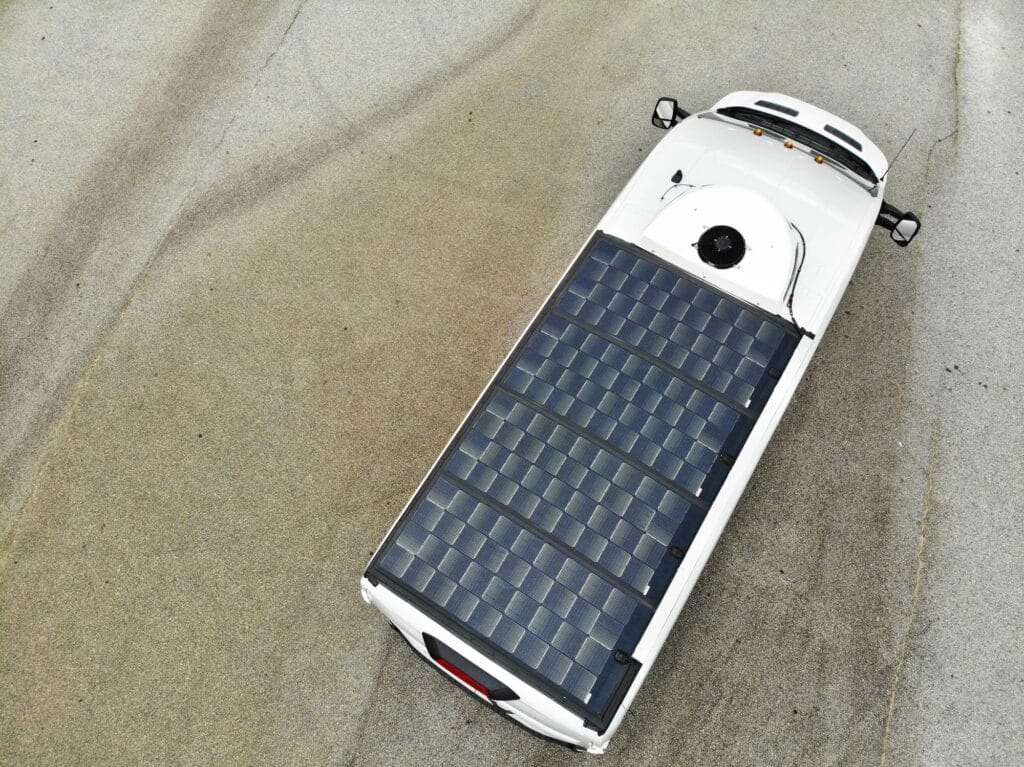
Not all solar is built the same. Most panels were designed for rooftops, but Merlin was designed for everywhere else.
From commercial fleets and refrigerated trailers to defense systems and autonomous maritime platforms, Merlin Solar’s patented technology is purpose-built for environments where conventional solar often fails. If it moves, flexes, vibrates, or operates off the grid, it needs a different solution.
Why Mobile Solar
Has To Be Different
Standard solar panels were designed for rooftops, and are flat, stationary, and predictable. The moment you put one on a truck, a trailer, a vessel, or a deployable shelter, the physics change immediately. Mobile and remote environments introduce a completely different set of stresses that conventional panels just aren’t built for such as:
- Continuous road vibration and mechanical shock that fatigues standard interconnects over time
- Surface flexing that cracks rigid glass-and-aluminum constructions
- Thermal cycling from -40°C to 120°C+ that standard test protocols don’t even cover
- Dynamic partial shading from bridges, cargo, and surrounding infrastructure that concentrates electrical stress
- Impact events that shatter conventional glass-framed modules entirely
The result is interconnect failure, hotspot formation, and power loss, which often happens before the system has had a chance to prove its ROI.
At Merlin Solar, our panels are engineered from the cell interconnection architecture upward, specifically for the conditions that break everything else.tent…

Merlin Solar Can Help If…
- You need reliable onboard solar for commercial trucks, trailers, or fleet vehicles
- You’re reducing idle time, fuel consumption, or engine hours across an entire mobile operation
- You’re integrating solar into a refrigerated transport or last-mile delivery system
- You’re building a deployable or off-grid power system that has to work in the field
- You need solar that survives vibration, impact, and thermal stress over a long service life
- You’re working on a defense, maritime, or aerospace application with zero tolerance for failure
- You have a specific, scaled need and are looking for an engineering partner, not a product catalog
Why Standard Panels Break Down in Motion
Most solar failures in mobile environments aren’t about cell degradation. The primary reason for failure all comes down to what connects them.
Interconnect Failure is the Real Culprit
Standard panels use soldered copper ribbons to carry current between cells. On a rooftop, that method works fine. On a vehicle, those solder joints are subjected to constant vibration and thermal cycling, expanding and contracting, flexing and fatiguing, until they eventually fracture.
Once a joint fractures, resistance at that point increases. Current gets forced through progressively smaller conductive pathways, generating localized thermal hotspots. Those hotspots accelerate metallization damage, increase resistive losses, and kick off a self-reinforcing degradation cycle that compounds over time. The system keeps running (just worse and worse) often with no visible warning until it fails completely.
This isn’t theoretical. Infrared thermal imaging of panels pulled from refrigerated trailers and Class 8 trucks consistently confirm hotspot signatures at the exact locations where solder joints have fractured.
What About Flexible Thin Film?
CIGS and other thin film technologies are frequently positioned as the flexible alternative to rigid glass panels. They do bend, but flexibility isn’t the same as durability, and in mobile environments this distinction is very important.
Thin film comes with its own set of problems:
- Lower power density, meaning you need significantly more surface area to generate the equivalent output
- High sensitivity to moisture ingress, which typically forces rigid glass-glass encapsulation, eliminating the flexibility advantage entirely
- Rapid degradation under partial shading, which is unavoidable in transportation environments
In documented field testing on a commercial truck cab fairing, a CIGS thin film module showed non-emitting regions, electrically isolated cells, and localized hotspot signatures after only just six weeks of deployment.
Flexibility without mechanical reliability isn’t a solution, it’s just a different mode of failure.
What Failure Actually Looks Like
Most solar panel problems are invisible until it’s too late. Electroluminescence (EL) imaging changes that.
EL imaging works by passing a current through a panel and capturing the light that it emits. Healthy cells glow uniformly. Damaged ones don’t. Electrical discontinuities, absorber damage, and hotspot formation all show up clearly in the image, often long before any measurable drop in output gives you a warning.
The Side-by-Side That Says Everything
In field testing on a Freightliner Cascadia cab fairing, a Merlin Solar crystalline silicon module and a CIGS thin film module were deployed under identical real-world conditions. Here is what the EL imaging showed:
CIGS thin film module after approximately six weeks of service: non-emitting regions, electrically isolated cells, localized hotspot signatures.
(Image – Merlin vs. CIGS thin film, Figure 2.4 from technical benchmark document)
Merlin Solar module after approximately four years of service: uniform emission, no measurable power degradation, no signs of damage.
Four years versus six weeks, under the same conditions, on the same vehicle. This isn’t a difference in quality control or manufacturing consistency, it’s a difference in architecture.
One system was built for this environment. The other wasn’t.
Get Ready
Are you ready to see what the right architecture can do for your operation?
More Energy, Even When Conditions Aren’t Ideal.
Standard solar panels are rated under ideal laboratory conditions, such as direct overhead sunlight, controlled temperature, and no shading, but mobile assets rarely see those conditions.
A truck travels east and west. Sun angles change throughout the day. Shadows from bridges, buildings, and cargo constantly interrupt irradiance. The real world doesn’t hold still, and your panels shouldn’t need it to either.
Merlin’s grid architecture is designed to effectively harvest energy across a much broader range of irradiance conditions than conventional modules. Here is what that looks like in practice:
- At 60° tilt with the sun to the side, Merlin delivers approximately 27% higher relative power output than a conventional 3-busbar module.
- With the sun behind the panel at 15° tilt, that advantage grows to approximately 35%.
- Across a full operating day, field data consistently shows approximately 20% higher total daily energy capture compared to legacy rigid and back-contact systems.
- Vehicles equipped with Merlin Solar achieve greater than 1.5x runtime for HVAC and hotel loads, leading to continuous operation through a standard 10-hour rest period without engine idling.
These are not laboratory projections. These are measured results collected across real commercial deployments, on real vehicles, in real operating conditions.
(Image: Time-of-day power output comparison and tilt angle performance graphs — Figures 2.3a, 2.3b, 5.1 from technical benchmark document)
How We Solved the Interconnect Problem
Rather than patching the weak points in legacy module designs, Merlin Solar developed a patented interconnection architecture that solves the problem at its very root. Our goal was to decouple electrical performance from mechanical stress entirely.
The Micro-Spring Interconnect
At the core of the system is the Micro-Spring interconnect. Instead of traditional soldered busbars, Merlin replaces rigid copper ribbons with a patented copper grid incorporating compliant micro-spring elements. These interconnects maintain continuous electrical contact while remaining thermo-mechanically decoupled from the silicon cell beneath them.
What that means in practice is that the module can flex, expand, and contract independently of the silicon substrate. Vibration does not transfer as stress. Temperature cycles do not fatigue the joints. The failure mode that limits every other mobile solar architecture simply doesn’t apply here.
The Numbers Behind It
In accelerated fatigue testing under cyclic mechanical loading, the results speak for themselves:
(Image: Micro-Spring architecture – Figure 3.1 from technical benchmark document)
450 Cycles
Approximate median fatigue life of standard soldered copper ribbon interconnects.
130,000+ Cycles
Median fatigue life of Merlin Micro-Spring interconnects.
That’s nearly three orders of magnitude improvement in fatigue resistance, under identical test conditions.
One architecture was built for this environment, while the other was adapted to it. The difference shows up in the data.
The Rebar Effect:
Built-In Redundancy
2,100+ Pathways. Zero Single Points of Failure.
Beyond the Micro-Spring interconnects, Merlin Solar incorporates redundant conductive grid networks on both the front and back surfaces of each crystalline silicon cell. The best way to think about it is like structural rebar in reinforced concrete. The grid distributes mechanical stress across the cell while also preserving electrical continuity at the same time.
Structural integrity
The grid network reinforces the silicon substrate, limiting crack initiation and propagation under mechanical loading.
Electrical redundancy
With more than 2,100 independent conductive pathways per module, electrical current automatically reroutes around damaged regions. A localized impact or cell fracture doesn’t cascade into power loss.
Shading resilience
In transportation environments, partial shading is unavoidable. Under those conditions, current redistributes automatically around shaded regions, minimizing stress concentration and reducing hotspot formation.
This architecture is also cell-agnostic. Because Merlin’s interconnection design doesn’t rely on rigid glass, heavy framing, or soldered stress-bearing interconnects, it can adopt future high-efficiency crystalline silicon cell technologies without requiring a redesign of the module architecture. The platform is built to evolve alongside the industry.
(Image: Accelerated interconnection fatigue testing under cyclic mechanical loading Figure 3.2 from technical benchmark document)
Merlin vs. Legacy Technologies
How We Compare
Not all solar architectures are created equal, and in mobile environments the differences aren’t subtle. Here’s how Merlin Solar stacks up against the two most common alternatives, back-contact crystalline silicon and thin film CIGS, across the performance dimensions that actually matter when your panels are in motion.
Power Density
Merlin Solar: Comparable to rigid crystalline silicon depending on configuration.
Back Contact: Comparable, but large-format cells introduce yield and fatigue challenges.
Thin Film (CIGS): Substantially lower. Requires significantly more surface area for equivalent output.
Mechanical Strength
Merlin Solar: Flexible and mechanically compliant with high fatigue resistance.
Back Contact: Susceptible to cell cracking and interconnect fatigue under vibration and thermal cycling.
Thin Film: Flexible in bending but highly susceptible to mechanical damage and coating fatigue.
Shading Resistance
Merlin Solar: Grid redundancy enables current rerouting under high shading percentages.
Back Contact: Partial shading induces damaging electrical bias and thermal stress.
Thin Film: Partial shading rapidly accelerates hotspot formation and irreversible failure.
Supply Chain
Merlin Solar: Compatible with standard crystalline silicon cell supply chain; multiple global sources.
Back Contact: Narrow, specialized manufacturing base with documented business continuity risks.
Thin Film: Limited material sourcing; moisture protection requirements drive rigid constructions.
Built to Survive in The Real World
Merlin Solar validates durability through test regimes that significantly exceed IEC and UL qualification requirements. Standard test protocols were designed for static utility-scale installations. They were not designed for the mechanical, thermal, and environmental realities of mobile operation. So we went further.
Vibration and fatigue
Merlin interconnects exceed 130,000 fatigue cycles versus approximately 450 cycles for conventional soldered copper interconnects.
Thermal cycling
Panels withstand cycling from -40°C to 120°C at four times standard IEC/UL acceleration, with minimal performance degradation.
UV exposure
Testing conducted at 19x standard IEC/UL ultraviolet exposure levels validates long-term electrical performance and structural integrity over a service life of up to 20 years.
Humidity freeze
Tested to 70 cycles versus the 10-cycle IEC/UL standard.
Dry heat
2,000 hours at 120°C versus the standard 200 hours at 105°C.

We’ll start with your problem and engineer from there.
Power degradation across all test conditions remains well below the -5% target threshold. These are not marginal passes. They are results with significant margin beyond qualification limits, across every dimension we tested.
(Image: Thermal cycling and humidity freeze degradation charts – Figures 4.2, 4.3 from technical benchmark document]
10 Billion Road Miles of Evidence
Since 2016, Merlin Solar systems have accumulated more than 100,000 vehicle installations and over 10 billion cumulative fleet road miles across long-haul, regional, and off-road duty cycles. The field evidence has remained consistent across all of our applications:
Idle reduction
Idle time reduced to less than 1% in Class 8 sleeper cab deployments, with full system ROI achieved within 15 months through fuel savings and reduced battery replacement costs.
Battery life extension
In fleets where deep-discharge events are the dominant battery failure mode, starter battery service life has been extended from approximately 18 months to 3-4 years.
Refrigerated transport range extension
A 6 kW Merlin system on a 48-foot reefer trailer allowed for continuous operation from Miami to Phoenix on a single shore power charge, reducing shore power consumption from approximately 200 kWh to 48 kWh.
Liftgate reliability
In a regional last-mile delivery deployment, zero liftgate battery failures were recorded over a three-year operating period, with projected service life extending beyond six years.
Severe impact survivability
In one documented incident, a Merlin panel installed on a truck cab fairing remained electrically functional and structurally intact after the vehicle struck an overbridge — continuing to generate power while stabilizing the damaged fiberglass structure
Performance is monitored through integrated telematics, providing fleet operators with real-time battery voltage and energy harvest data. Merlin-equipped fleets consistently maintain average battery voltages above 13.2V, even during prolonged inactivity.
Built for Mobile, Ready for Anything.
Merlin Solar isn’t limited to a single vehicle type or specific application. The same architecture that survives 10 billion road miles on Class 8 trucks can easily scale across a wide range of different mobile and deployable platforms. If it moves, flexes, or operates far from the grid, the engineering principles behind Merlin still apply.
Commercial transportation
From Class 8 sleeper cabs and refrigerated trailers to last-mile delivery vans, liftgates, and electric box trucks, Merlin systems are deployed across the full spectrum of commercial fleet operations.
Applications include idle mitigation, starter battery maintenance, eTRU efficiency, liftgate reliability, and EV auxiliary load support. Across every configuration, the goal is to reduce operating costs and keep the asset running.
Defense and tactical
In remote and demanding environments, power infrastructure is either unavailable or a liability. Merlin systems integrate into deployable tents, relocatable containers, and tactical vehicles to provide immediate, reliable power without fuel dependency.
Lightweight form factor and rapid deployment capability make them a practical fit for forward operations where setup time and logistical footprint matter.
Maritime
Merlin panels are deployed on uncrewed ocean drones and autonomous surface vessels operating in some of the most demanding conditions on the planet.
Constant saltwater spray, hurricane-force winds, and continuous mechanical stress are not exceptions, they are the operating reality. Merlin’s architecture is built to handle all of it while keeping navigation systems, sensor arrays, and onboard electronics fully powered and operational.
Space
At high altitude, the environment becomes extreme in ways that ground-level testing can’t fully replicate. Merlin technology is deployed on high-altitude balloons where UV radiation intensity, thermal shock, and atmospheric pressure create failure conditions that conventional panels just aren’t equipped to survive.
The same interconnect architecture that handles road vibration can handle the stratosphere.
Off-grid and disaster relief
When the grid is not an option and setup time is critical, the lightweight peel-and-stick form factor of Merlin panels allows for rapid deployment across a wide range of different structures and surfaces.
From relocatable containers to deployable shelters, Merlin provides reliable power in the locations and situations where it’s needed the most and available the least.
Stop Replacing Panels And Start Engineering the Right Ones
Tell us what you need to power, where it needs to operate, and what it needs to survive.
We’ll start with your problem and engineer from there.
Frequently Asked Questions
Standard solar panels are built on rigid glass-and-aluminum frames optimized for static rooftop installations. In mobile environments, continuous vibration, thermal cycling, and mechanical shock cause the soldered interconnects inside conventional panels to fracture over time. This leads to hotspot formation, power loss, and eventual failure. Merlin Solar’s Micro-Spring interconnect architecture eliminates this failure mode by mechanically decoupling the electrical connections from the silicon cell.
Most flexible solar panels use thin film technology, which trades mechanical flexibility for lower power density and high sensitivity to shading and moisture. Merlin Solar uses high-efficiency monocrystalline silicon (the same cell technology in premium rooftop panels) combined with a patented copper grid and Micro-Spring interconnects. This gives you the durability of a flexible form factor without the performance compromises of thin film.
Merlin’s grid architecture provides over 2,100 independent conductive pathways per module. Under partial shading, current automatically reroutes around shaded regions rather than concentrating stress at a limited number of conductors. Field data shows approximately 20% higher total daily energy capture compared to legacy rigid and back-contact systems, with performance advantages of 10-15% during morning and late-afternoon low-angle irradiance periods.
Merlin Solar validates durability through test regimes that significantly exceed IEC and UL qualification requirements: interconnect fatigue testing to over 130,000 cycles (versus ~450 for standard interconnects), thermal cycling from -40°C to 120°C at 4x standard acceleration, UV exposure at 19x standard levels, humidity freeze testing to 70 cycles (versus 10 standard), and dry heat exposure for 2,000 hours at 120°C (versus 200 hours standard). Performance degradation remains well below qualification thresholds across all conditions.
In Class 8 sleeper cab deployments, full system ROI has been achieved within 15 months through fuel savings and reduced battery replacement and maintenance costs. Idle time has been reduced to less than 1% in documented fleet deployments, and starter battery service life has been extended from approximately 18 months to 3-4 years in fleets where deep-discharge events are the primary failure mode.
Yes. Merlin Solar systems can support gasoline, diesel, CNG, hybrid, and all-electric powertrains. In electric vehicle fleets, Merlin solar arrays provide dedicated energy generation for auxiliary systems, such as refrigeration units, liftgates, HVAC, offloading those loads from the primary traction battery and extending vehicle operating range without adding weight from additional battery capacity.